A-PHY
Frequently Asked Questions
Resources
Introduction to MIPI A-PHY
-
What is MIPI A-PHY?
MIPI A-PHY (originally released to members in September 2020) is the first standardized, asymmetric, long-reach serializer-deserializer (SerDes) physical layer specification targeted for advanced driver-assistance systems (ADAS), autonomous driving systems (ADS), in-vehicle infotainment (IVI) displays and other surround-sensor applications (e.g., cameras, lidar, radar).
A-PHY's primary mission is to transfer high-speed data between cameras and displays and their related ECUs.
A-PHY offers:
- High reliability: Ultra-low packet error rate (PER) of less than 10-19 for unprecedented performance over the vehicle lifetime
- High resiliency: Ultra-high immunity to EMI effects in demanding automotive conditions
- Long reach: Up to 15 meters
- High performance: Data rate as high as 16 Gbps with v1.0; up to 32 Gbps with support for Star Quad (STQ) cables in v1.1
-
What is an automotive SerDes?
A serializer/deserializer converts parallel data to serial data (and vice-versa) for fast communication between devices using lower cost cables and connectors. As data rates and speeds increase, SerDes designs become increasingly complex, especially when designing to meet automotive reliability, quality, aging and functional safety requirements.
-
Why is a standardized SerDes specification needed for automotive applications?
Prior to the release of MIPI A-PHY, the industry did not have a standard for a long- reach SerDes with the performance, noise immunity and reliability to cover long-distance, high-speed sensor and display links. Sensor links are particularly susceptible to electromagnetic interference, data loss and latency as link bandwidth and distance increase. As such, there is a need for a standard that meets stringent EMC requirements and offers stricter testing to guarantee proper performance and high resilience.
Currently, MIPI CSI-2® and DSI-2℠ are used extensively within automotive applications. However, without a long-reach physical layer SerDes standard, MIPI protocols have been connected through proprietary "bridge" solutions, adding complexity and design costs, and the inability to source multiple vendors and achieve economies of scale. In addition, there has not been a standard that includes provisions for functional safety and security within the interface design.
-
What are the key differentiators of MIPI A-PHY?
The primary benefits of A-PHY are:
- A-PHY supports long cable lengths and a high data rate.
- A-PHY has enhanced noise immunity.
- A-PHY has an ultra-low packet error rate < 10-19.
- A-PHY has higher than a 90% net data rate.
- A-PHY can be fully implemented in hardware -- no software stack is required as in some solutions.
- Designed for use with widely implemented protocols and interfaces.
- A-PHY is the first asymmetric industry-standard solution. Most other solutions are proprietary.
-
Does A-PHY support MIPI CSI-2 and DSI-2?
Yes. MIPI A-PHY is the only long-reach SerDes standard to support CSI-2 and DSI-2. All available MIPI CSI-2 and DSI-2 versions are supported via protocol adaptation layers (PAL/CSI-2 and PAL/DSI-2).
-
Does A-PHY support non-MIPI interfaces?
Yes. MIPI A-PHY supports approved third-party protocols. For instance, as part of this effort, protocol adaptation layers (PALs) have been released for VESA’s DisplayPort and Embedded DisplayPort standards (VESA DP and eDP), as well as for I2C and GPIO. Additional PALs are scheduled to be developed for Ethernet and I3C.
-
Does MIPI A-PHY also support video compression such as VESA-DSC?
Yes it does. If you use MIPI DSI-2 over A-PHY, it supports VESA-DSC and VDC-M compression. More information can be found in this presentation from the MIPI Automotive Workshop.
-
What is the distance (range) that A-PHY can reach? Is it possible to go longer distance at a reduced performance?
MIPI A-PHY can reach up to 15m using coaxial cable with up to four inline connectors. There is no lower limitation for distance. For any other channel, system simulation should reflect the specific system implementation capabilities.
-
What data rates are supported?
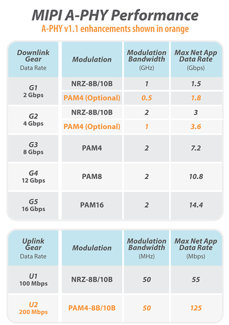
MIPI A-PHY v1.0 supports five speed gears (2, 4, 8, 12 and 16 Gbps) to provide design flexibility.
A-PHY v1.1 doubles the total downlink bandwidth from 16 to 32 Gbps by adding support for Star Quad (STQ) cables that provide dual differential pairs of conductors within a single shielded jacket. This enables two A-PHY ports over a single cable, saving cost, weight and complexity compared with using two separate coaxial or shielded twisted pair cables.
-
What connection topographies can A-PHY support?
MIPI A-PHY can support direct and daisy-chained connections.
-
Does A-PHY support ISO 26262 functional safety?
Yes, MIPI A-PHY is defined to support the required functional safety requirements per ISO26262:2018, including message counter, CRC-32, keep-alive mechanism and other provisions to enable creation of a system-level, end-to-end solution.
-
Will A-PHY replace Ethernet and other technologies in automotive?
No. As MIPI A-PHY is designed as a high-speed asymmetric solution, it can complement and be integrated with other network backbones such as Ethernet, CAN, FlexRay and other interfaces.
-
When will MIPI A-PHY will be implemented in automotive?
Industry implementation is expected by 2024. MIPI expects samples to be available prior to 2024.
-
Is further development planned for MIPI A-PHY?
Yes. A-PHY v1.1 was adopted in December 2021, and the A-PHY Working Group has begun requirements gathering for future releases with data rate increases to 48 Gbps and beyond.
-
How does A-PHY fit into MIPI’s automotive efforts?
A-PHY serves as the foundation of MASSSM (MIPI Automotive SerDes Solutions), a family of specifications that when complete, will provide automotive OEMs and their suppliers with end-to-end high-performance connectivity solutions for the growing number of cameras, sensors and displays that enable automotive applications.
More specifically, MASS allows the higher-layer protocols from MIPI (such as MIPI CSI-2 and DSI-2) and third parties (e.g., VESA eDP/DP) to operate over A-PHY physical links spanning an entire vehicle, eliminating the need for proprietary “bridges” and PHYs. For OEMs and system integrators, this equates to simplified in-vehicle networks (i.e., cable harnesses) and reduced costs, weight and development time. System-level engineers will be able to use this architecture to build systems that meet ASIL (Automotive Safety Integrity Level) requirements at any level, from ASIL B to ASIL D. MASS also will provide end-to-end security to include authentication, integrity and confidentiality for data protection of camera, sensor and display components. Learn more about MASS.
-
Why was A-PHY adopted by IEEE and what are the benefits of IEEE adopting the interface?
In 2021, IEEE adopted A-PHY v1.0 as IEEE 2977-2021. IEEE is the world's largest technical professional organization dedicated to advancing technology for humanity. A-PHY was adopted because the organization recognized the value that a standardized SerDes interface would offer to the automotive industry. A key benefit of IEEE adopting A-PHY is that it gives non-MIPI members access to the specification, allowing potential implementers to evaluate the interface without requiring them to become a MIPI member. Now that it has been formally adopted by the MIPI Alliance, v1.1 will also be brought forward for adoption as an IEEE standard.
Performance
-
How are the gears structured?
A-PHY supports two noise/performance profiles (P1 and P2), with full inter-profile interoperability, as shown in the table below:
- Profile 1 (P1): Optimized for low cost/power implementations for the lower speed gears with lower noise immunity and target BER of <10-12
- Profile 2 (P2): Optimized for the vehicle lifespan, with link robustness for all speed gears with high noise immunity and target PER of <10-19. All gears working in Profile 2 are tuned for performance and high noise immunity.
-
What will be the number of data lanes for a typical A-PHY port?
A typical A-PHY port will support:
- v1.0: 1 data lane (providing maximum data rate of 16 Gbps)
- v1.1: 2 data lanes (providing maximum data rate of 32 Gbps)
-
Do eye diagrams have to be defined for the various speed gears?
For A-PHY Profile 1, which is based on NRZ Physical Medium Dependent (PMD), the A-PHY specification provides eye diagrams for all supported gears (G1-G3). For Profile 2, which is based on PAM, eye diagrams are not appropriate.
Power Spectral Density (PSD) limits are specified for all gears, along with requirements for supporting mandatory test modes for transmit jitter and linearity to fully characterize the transmitter.
-
How is the packet implemented in MIPI A-PHY?
The A-Packet is structured to carry the native protocol data and all information that the A-PHY Data Link Layer requires to perform its functions efficiently.
The A-Packet has following features and functions:
- Downlink and uplink use the same packet structure.
- The structure is optimized supporting multiple protocol aggregation with minimal overhead and latency.
- The A-Packet header contains all required information (e.g., QoS, Priority, Destination, Protocol Type).
- The A-Packet structure:
- Header: 8 byte including MC (message counter) and header CRC (Cyclic Redundancy Check)
- Payload
- Tail: 4 Byte (CRC-32)
-
How are packet retransmissions handled with data sources, such as cameras, continuously transmitting data?
The retransmission is handled at the A-PHY level and is transparent to the upper layer. A-PHY has a retransmission buffer to handle camera stream with up to three retries. The net application data throughput already takes care of the retransmission; no additional buffering is required at the MIPI CSI-2 level. More information can be found in the MIPI A-PHY specification.
-
How does one detect packet headers?
Search for 8-byte packet header with message counter (MC) and the header CRC (Cyclic Redundancy Check) and a packet tail with 4-byte CRC-32.
-
Is there error correction for the packet header?
The A-PHY packet header with the message counter has CRC (Cyclic Redundancy Check) and the packet tail has CRC-32.
-
How is error correction handled for existing nodes? For example, MIPI CSI-2 has an ECC field whereas A-PHY is CRC. Is there error correction for the packet header, and how does one detect packet headers?
There should be no need to transport any legacy packet headers; just use the A-PHY native mechanism.
System Features
-
What features are implemented in A-PHY to make a robust system?
Features for a robust system include:
- High-speed downlink and aggregation to support multiple 4K cameras and displays
- Asymmetric high-speed link with fixed low latency ~6μs for Gear 5, resulting in a PER of less than 10-19 (which is equivalent to 1 packet error in ~10,000 car-lifetimes)
-
What are the principal features of the A-PHY physical layer?
A-PHY layer has the following features and functions:
- Unified structure to reduce complexity
- Shared 8B/10B Physical Coding Sublayer (PCS) for speed Gear 1 and 2 and uplink channel.
- Retransmission (RTS) sublayer (local retransmission mechanism):
- Manage data packing and buffering
- Assign message counter (MC) and CRC (Cyclic Redundancy Check)
- In Profile 2: the retransmission process for A-Packets that are erroneous or that are not received
- Physical Coding Sublayer (PCS):
- Specifies the conversion of Data Link Layer A-Packets into PHY symbols
- In Profile 2, PCS also handles the Just In Time Canceller (JITC) retraining
- Physical Media Dependent (PMD) sublayer:
- Defines the electrical specifications and the physical medium
-
What are the principal features of the A-PHY data link layer?
The A-PHY Data Link Layer is a protocol-agnostic layer that performs scheduling, prioritization and forwarding of A-Packets.
- Each protocol adaptation layer has at least one A-PHY protocol interface (APPI) connection to the A-PHY Data Link Layer.
- The A-PHY Data Link Layer may be connected to multiple protocol adaptation layers using a single local function.
- The A-PHY Data Link Layer may have a single A-PHY network function connected to it, or multiple A-PHY network functions.
-
How many operating modes are there in A-PHY?
There is an active mode consisting of Normal state and Start-up state; a non-active mode consisting of Sleep state and Power-up state and a Test mode.
-
How much power (and at what voltage) can be realistically delivered over the A-PHY interface?
MIPI A-PHY can deliver:
- Power: 6W max
- Voltage: 8V-13V
- Current: 0.75A MIN
-
Can the sync signal be used to provide the clock?
Nothing in the specification prevents using the sync signal as the clock.
-
Will the expected startup time be in the 100-200 milliseconds range?
Startup time is up to 100ms.
-
Can we achieve bandwidths of 20 Gbps, 25 Gbps in automotive with today's connectors and wiring?
With STQ /HSD dual lanes, yes. This is now available with A-PHY v1.1, and even higher speeds will be addressed in future releases using similar cabling.
-
Is PCIe tunneling supported?
PCIe tunneling is not presently supported. MIPI A-PHY is highly asymmetric, with high bandwidth in one direction and low bandwidth in the other (i.e., 16 Gbps in one direction and 100Mbs in the other for A-PHY v1.0).
Cabling
-
What types of cables are defined for A-PHY? Is UDP possible?
MIPI A-PHY v1.0 defines coax or SDP (shielded differential pair) cables. There is nothing in the specification that prevents UDP (unshielded differential pair) implementation.
A-PHY v1.1 doubles the total downlink bandwidth from 16 to 32 Gbps by adding support for Star Quad (STQ) cables that provide dual differential pairs of conductors within a single shielded jacket. This enables two A-PHY ports over a single cable, saving cost, weight and complexity compared with using two separate coaxial or shielded twisted pair cables.
-
What is link distance at PAM16?
The channel length is independent of the Gear and PAM level. It is 15m for coax and 10m for STP and STQ cables.
-
What cable loss does the MIPI A-PHY specification assume?
Cable loss is modeled in the A-PHY channel model, the values used in this model were based on available data for cables and connectors recommended by various OEMs.
-
Which type of cable diagnostics and cable fault detection is planned?
A-PHY provides information on link quality and multiple indicators on channel status that can be used by the application per user definition.
-
Does the specification define the end node connector interface?
Yes. The specification for the connector is part of the complete end-to-end channel definition.
Communications and Noise Immunity
-
Does the A-PHY specification cover communication link requirements (e.g., s-parameters)?
All the communication link requirements are covered within the A-PHY specification (e.g., return loss, insertion loss, etc.). There is a clear definition for the channel, with the parameters required to design transmitters and end receivers for MIPI A-PHY.
Note: A channel model for simulation is available that can be used by MIPI members for validation.
-
What level of noise immunity is supported?
EMC requirements vary by OEM. Some aim for minimal noise immunity, while others apply stringent requirements to protect their systems.
The two A-PHY performance profiles provide two noise immunity levels to accommodate this variance:
- Profile 1 (P1) has lower noise immunity, similar to other SerDes solutions, and is applicable for speed Gears 1 and 2 (and optional Gear 3).
- Profile 2 (P2) has very high noise immunity based on analysis of the expected noise level over a vehicle’s lifetime.
MIPI conducted multiple tests in an independent lab to evaluate how the noise levels and shielding affect degradation after mechanical stress and aging. The results helped in the evaluation of the different available technologies, and research continues as part of the A-PHY Working Group's activities.
-
Is there a noise profile to implement the Narrow Band Interference Canceller (NBIC) feature?
NBIC is part of the A-PHY specification. An application note has been created by the A-PHY working group to define a noise profile for the various noise sources in the system. The noise profile has been used by multiple companies to validate and test possible solutions.
Involvement in MIPI A-PHY development
-
How can I get involved with MIPI A-PHY or MASS?
Learn more about MIPI A-PHY and MASS. MIPI Adopter members can download the specification and view available resources, and MIPI Contributor members may also join the A-PHY Working Group to receive communications and participate in development work.


